REEL TO REEL PLATER
REEL TO REEL PLATER
Available quantity:1
Description
REEL TO REEL PLATER
Basic Description:
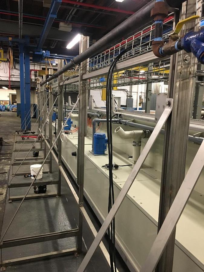
Built in 2017 by Polytech MFD., this line was designed to tin plate 5” strip stock material in reel to reel format. The line consists of 15 total tank modules: Soak clean, electro- clean, acid pickle, 11 tin plating modules and a final rinse. Each module contains 2 working cells. Internal cell construction will support strip stock widths up to 7” and surface areas up to
2.3 square feet per cell. Though built for a target plating speed of 10-25 FPM on sputtered nickel strip, this line has much higher throughput capacity based on substrate being processed as well as desired plating type and finish.
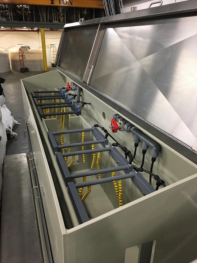
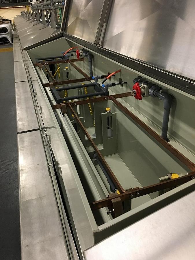
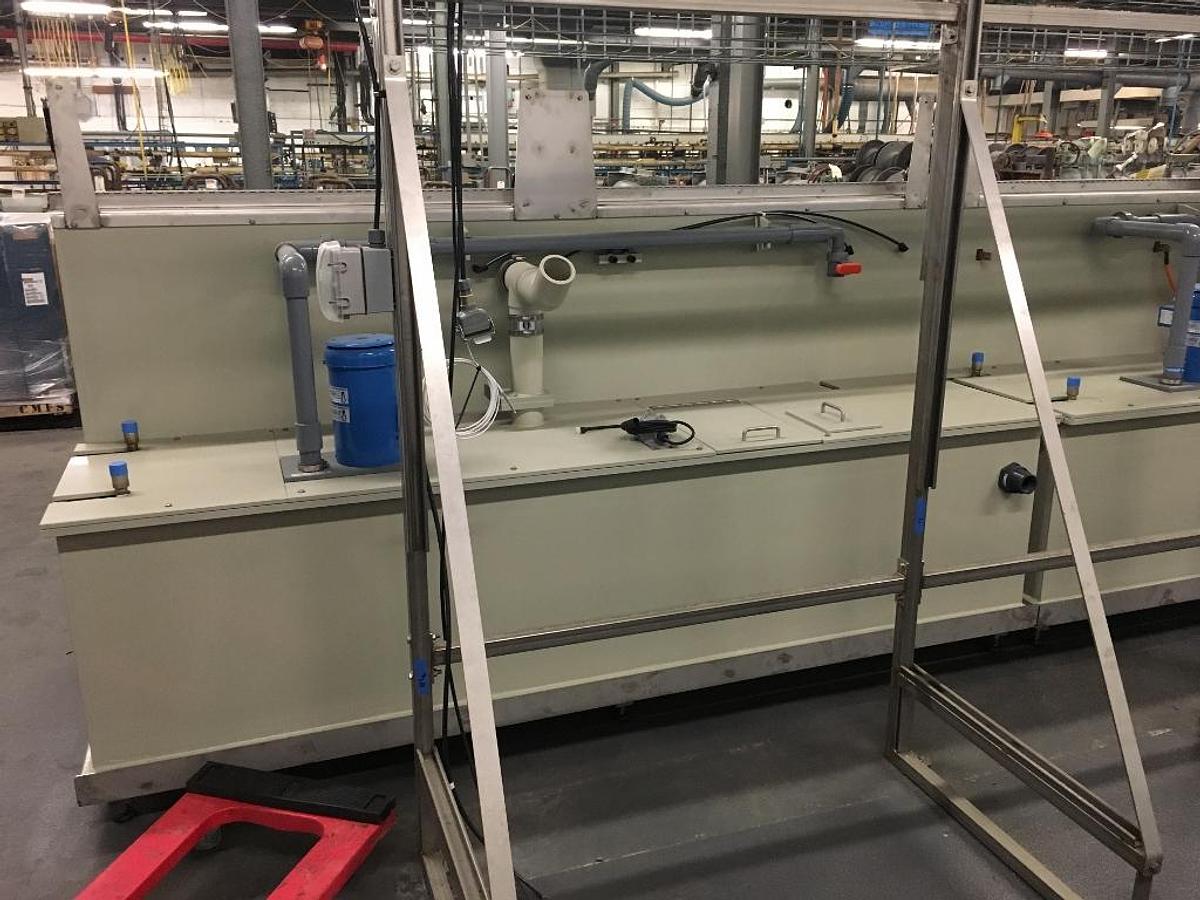
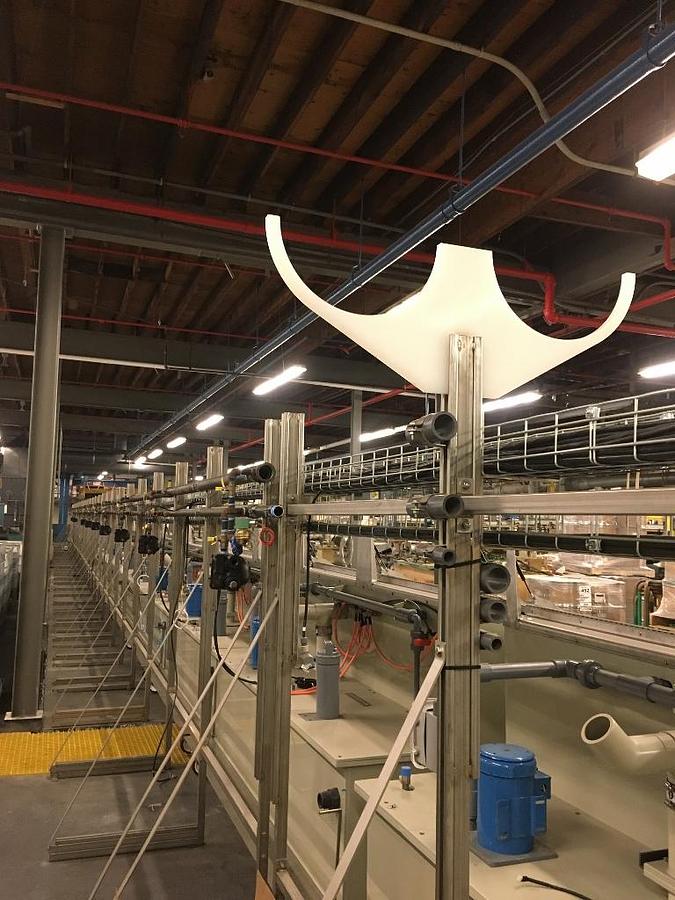
The line was constructed to be modular in nature, having stationary tank sections for the soaps, acid and final rinse, while all 11 plating modules are on wheel mounted, moveable framework thus allowing for customization of the process, addition or subtraction of other plating type or process modules.
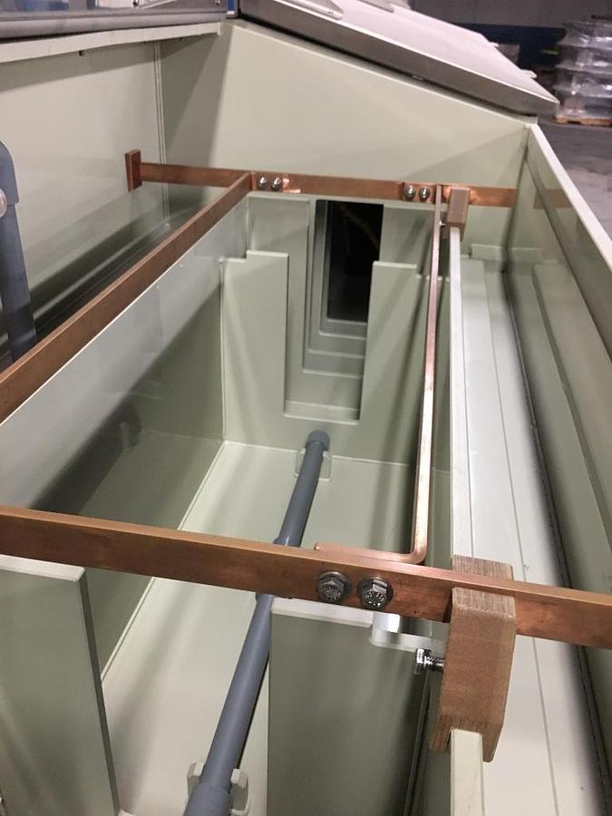
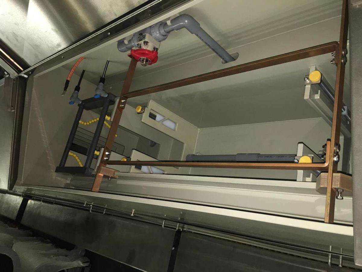
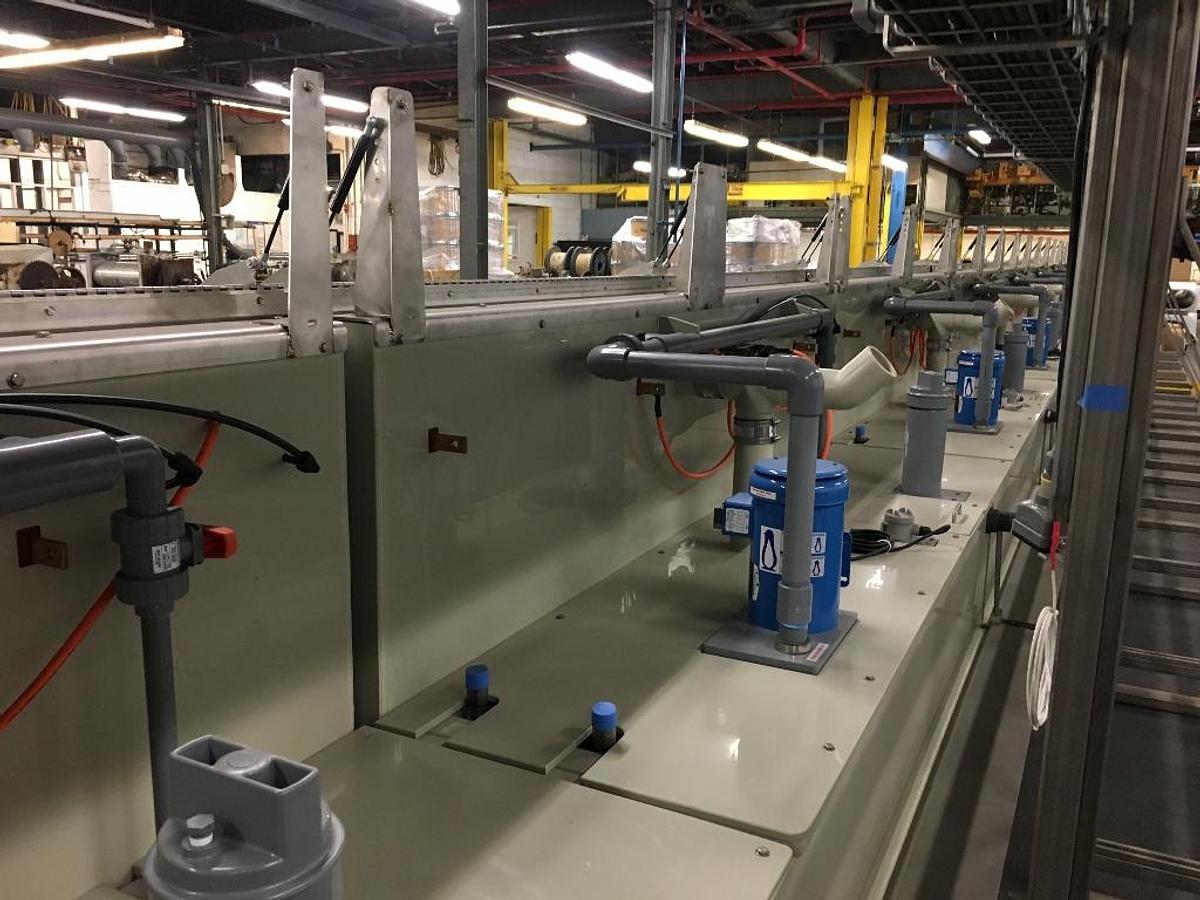
Each module is constructed on a “tank within a tank” premise, having a 100 gallon volume capacity hold tank within its own containment structure; volume from the solution hold tank is pumped into the working cell, flowing across the work within the cell and draining back to the hold tank. Individual tank level sensors monitor tank level and temperature within solution hold section of each module. The modules are accessible from the top via self supporting lids, 1 over each cell section. Module plumbing is accessible by quick mount panels affixed to the front of each unit, 1 panel for each cell section.
This line was never used in production nor filled for a site acceptance test (it has been factory leak tested). The line was fabricated and installed for a project that lost funding at the last minute. As such, there are minor details in need of completion to make the line functional (there are a few water and steam solenoids yet to be installed as well as wiring such as electrical pig tails from the filtration and transfer pumps in need of connection).
Dimensions:
Line footprint in its current configuration including the utility raceway for electrical, steam and plumbing as well as the operator step included on the front of each module is 91” wide x 133’ 11” long x 84” tall.
Utility raceway measures 31” wide at the base and 84” tall, right triangle configuration.
Tank modules are 48” wide x 48” tall (60” tall including pneumatic module lid support). Module length varies by function:
• Soak clean, electro-clean and all 11 plating modules – 102” long
• Acid pickle module – 124” long
• Final rinse module – 105” long
Individual Module Description:
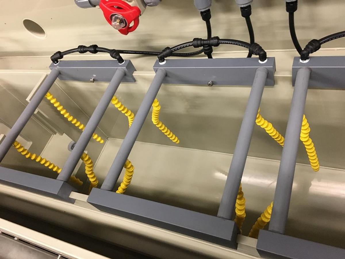
• Module #1, Soak Soap: 2 work cells each measuring 12” wide x 24” long x 12” deep; 4 nozzle flex-loc air blow off station after each cell adjustable for position and valved for volume control; Process Technology Model 2G12 level control and Process Technology LC Level Switch indicator with low level alarm for main solution holding tank; Penguin model 2X PAK solution circulation pump with individually gate valved cell flow control ending in a solution sparge bar mounted to cell bottom; module has a single blast gate damper for volume control of emissions from working cell area as well as hold tank area; single loop thin wall zirconium steam heating coil adjacent hold tank bottom – loop is approximately 4’ long and 1” diameter. Module has a self-supporting hinged lid over each cell section (2 lids) and a quick access panel for each cells plumbing (2 panels).
Tank drain outlet is 1 ½” bulkhead with 1 ¼” NPT male nib.
• Module #2, Electroclean: 2 work cells each measuring 12” wide x 24” long x 12” deep; 4 nozzle flex-loc air blow off station after each cell adjustable for position and valved for volume control; Process Technology Model 2G12 level control and Process Technology LC Level Switch indicator with low level alarm for main solution holding tank; Penguin model 2X PAK solution circulation pump with individually gate valved cell flow control ending in a solution sparge bar mounted to cell bottom; module has a single blast gate damper for volume control of emissions from working cell area as well as hold tank area; single loop thin wall zirconium steam heating coil adjacent hold tank bottom – loop is approximately 4’ long and 1” diameter. Module has a self-supporting hinged lid over each cell section (2 lids) and a quick access panel for each cells plumbing (2 panels).
Tank drain outlet is 1 ½” bulkhead with 1 ¼” NPT male nib. Each cell is anodically bussed with 1” x ¼” copper insulated from cell walls by machined garolite stand-offs; bussing is also through-wall insulated at its entry point on the back of the module. 600V insulated, lugged flexible cable to cathode connection – cathode connections are not present.
• Module #3, Acid Pickle: 2 work cells each measuring 12” wide x 24” long x 12” deep; one 8 nozzle flex-loc air blow off station before the acid cells and one 8 nozzle flex-loc air blow off station after the acid cells, each blow off line adjustable for position and valved for volume control; Process Technology Model 2G12 level control and Process Technology LC Level Switch indicator with low level alarm for main solution holding tank; Penguin model 2X PAK solution circulation pump with individually valved cell flow control ending in a solution sparge bar mounted to cell bottom; module has a single blast gate damper for volume control of emissions from working cell area as well as hold tank area; single loop thin wall zirconium steam heating coil adjacent hold tank bottom – loop is approximately 4’ long and 1” diameter. Module has a self-supporting hinged lid over each cell section (2 lids) and a quick access panel for each cells plumbing (2 panels). Tank drain outlet is 1 ½” bulkhead with 1 ¼” NPT male nib.
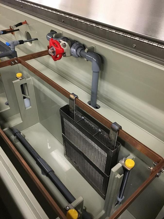
• Module #4 - 14, Tin Plate (11 identical modules): 2 work cells each measuring 12” wide x 24” long x 12” deep; individual cell operating level control via adjustable overflow gates; 4 nozzle flex-loc air blow off station after each cell adjustable for
position and valved for volume control; Process Technology Model 2G12 level control and Process Technology LC Level Switch indicator with low level alarm for main solution holding tank; Penguin model 2X PAK solution circulation and filtration pump with individually gate valved cell flow control ending in a solution sparge bar mounted to cell bottom; Penguin model 3CN-2A filter chamber accepts a single 20” spun wound cartridge filter; module has a single blast gate damper for volume control of emissions from working cell area as well as hold tank area; single loop thin wall zirconium steam heating coil adjacent hold tank bottom – loop is approximately 4’ long and 1” diameter. Module has a self-supporting hinged lid over each cell section (2 lids) and a quick access panel for each cells plumbing (2 panels). Tank drain outlet is 1 ½” bulkhead with 1 ¼” NPT male nib. Each cell is anodically bussed with 1” x ¼” copper insulated from cell walls by machined garolite stand-offs; bussing is also through-wall insulated at its entry point on the back of the module. 600V insulated, lugged flexible cable to cathode connection – cathode connections are not present. Modules #4-14 are built on mobile, locking wheel bases with quick disconnects for all utilities.
• Module #15, Final Rinse: 2 work cells each measuring 12” wide x 36” long x 12” deep; 12 nozzle flex-loc air spargers within each rinse cell adjustable for position and valved for volume control; Process Technology Model 2G12 level control and Process Technology LC Level Switch indicator with low level alarm for main solution holding tank; Penguin model 2X PAK solution circulation pump with individually gate valved cell flow control ending in a solution sparge bar mounted to cell bottom; module has a single blast gate damper for volume control of emissions from working cell area as well as hold tank area; single loop thin wall zirconium steam heating coil adjacent hold tank bottom – loop is approximately 4’ long and 1” diameter. Module has a self-supporting hinged lid over each cell section (2 lids) and a quick access panel for each cells plumbing (2 panels). Tank drain outlet is 1 ½” bulkhead with 1 ¼” NPT male nib.
Exhaust/Scrubber:
This line is serviced by 2 MAPCO model MW-200 wet scrubbers with integral, top mounted variable speed exhaust fans. Each scrubber is designed for 4,000 CFM of exhaust capacity with 3 feet of packing, 1 chevron mist eliminator, 1 mesh pad mist eliminator and a continuous blowdown of 0.12 gpm. Each scrubber/exhaust fan package also contains a sump box for blowdown collection, liquid level controls and transfer pump. Additional details, construction and dimensional specifications can be found in attachments A and A1. Twelve, 20’ lengths of 13” ID PVC duct is available to support exhaust system installation.
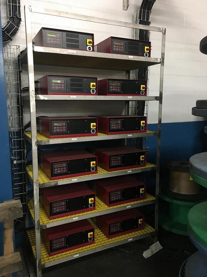
Rectification:
A 12 unit bank of model Q100-12-100-480 Baker Technology Associates rectifiers provide DC power to the line, servicing the electro-clean module and all 11 tin plating modules;1 rectifier per module. The rectifiers are identical in manufacture, non-contact air cooled with an output of 12 Volts and 100 Amps, AC input f 480V. Rectifiers have integral amp-hour monitoring and totalizing with direct 110V connection for dosing pumps, ramp control, and ripple of less than 2%. Additional details, construction and dimensional specifications can be found in attachment B. All rectifiers are housed remotely from line on a single vertical rack.
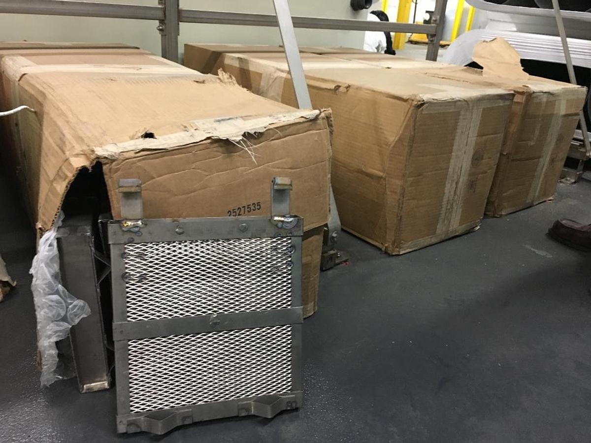
Anode Baskets:
Titanium anode baskets total 108 units, measuring 10” wide x 11” tall x 1.5” thick. Basket hooks are 2” long x 1” wide and ¼” thick. Wall construction is expended metal mesh with girth bands and support rods.
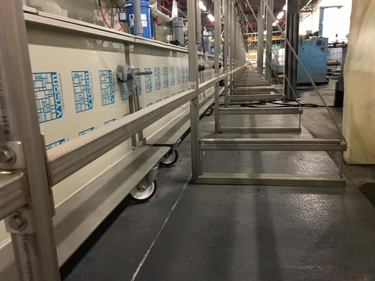
Utility Raceway:
A central utility raceway runs in parallel to the line, positioned immediately behind the line to carry all line electrical, steam and water supply to/from the line. All electrical is carried down the raceway in a basket style cable tray which extends to the main control panel. Water and steam plumbing is affixed to the raceway via plumbing hangers and straps. Raceway is of bolt together construction with bolt tabs on the bottom of each upright for securing to the floor.
Line controls:
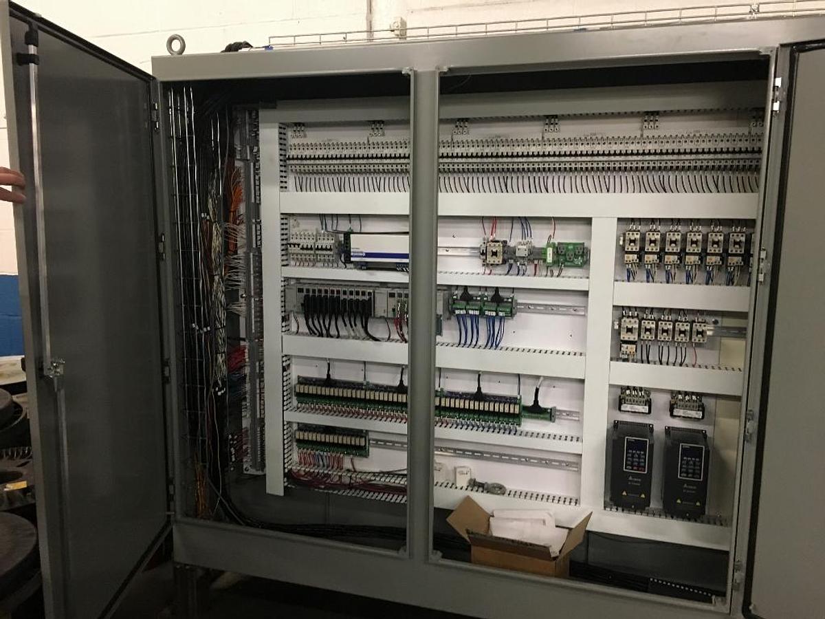
A single main control panel houses all line electrical feeds, submersible RTD temperature probe signal I/O, 4-10mv level control signal I/O, solenoid output connections, all 110V power output, relays, VFD, PLC, misc. controllers and programming interface connection ports. The main control panel is connected to a remote operator podium which has touchscreen operator interface. The remote operator control houses all line start up and operating switches. Hardware for line control is Automation Direct Productivity2000 micro-modular programmable controller with analog I/O. Control program and parameters were written by Schmidt Electric of Naugatuck, CT.
The remote operator touchscreen control interface is paginated minimally for:
• Line start/stop
• Transfer pump engage/disengage
• Rectifier controls and status
• Individual Module Level and Temperature alarms
• Exhaust system start/stop
System is capable of vast expansion to control logic, automated sensing, dosing and multitudinous data outputs.
Line Materials of construction:
• Modules, internal hold tanks and working cells: ¾” thick Euro-grey Polypropylene
• Utility raceway framework: 316 Stainless Steel
• Floor mount module positioning track: 316 Stainless steel
• Tank lids: 316 Stainless Steel
• Plumbing access panels: 316 Stainless Steel
• Operator steps: 316 Stainless Steel
• Filter chamber housings: CPVC
• Electrified tank bussing: 1” x ¼” copper
• Level switches: 316 Stainless Steel, FRP
• Anode baskets: Titanium
• Steam plumbing: black iron w/traps
• Solution plumbing Schd. 80 PVC
• HVLP Air: Polyethylene
• Line hardware: 316 Stainless Steel, Nylon
Specifications
| Condition | New |
| Stock Number | 1565 |